|
Candy Cane Project
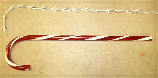
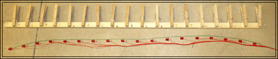
Sitting in the Christmas warehouse, I had 100 pre-lit red candy canes in boxes that I had purchased a few years back. I decided to do something with them and I didn’t want to have to try to line them all in a row and keep them straight. I ended up using 84 candy canes. Using six 2x6x8 and placing a door hinge between each two sections so I ended up with three sections of 16’ hinged in the center. Measuring the spacing of the candy cane and calculating the number of candy canes would fit in the 8’ section. That number came out to 14 candy canes per 8’ section with 6 sections totaling 84.
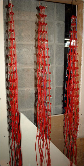
I wanted to add my twist to this yard element and just having each candy cane on its own channel was too easy. I decided to make each candy cane have each light be controlled separately. So I measured the length of the candy cane 36” and divided that number by 2 (2” spacing between each light). That number was 18. So each candy cane would have 18 lights. So with 18 lights and 84 candy canes that would total 1,512 lights and channels.
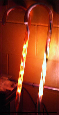
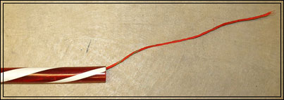
Now the question would be type of lights or LEDS will I be using. I first tried 8mm bright straw hat LEDS. I made one string and the light beam from the 8mm straw hat was too narrow and it washed out the red plastic on the candy cane. So I tried 8mm red LEDS and the outcome was what I was looking for.
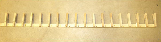
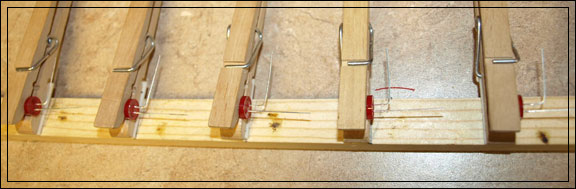
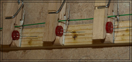
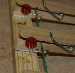
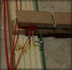
With the color picked, the total of LEDS that I need for each candy cane and total. Now I need to figure out how I’m going to solder 1,512 LEDS with 2 legs on each led. Yes, that is over 3,000 solder joints just for the led strings. I made a jig to hold the 18 LEDS spaced 2” apart. The jig is made of piece of wood that is the length of the candy cane that will hold 18 LEDS using clothes pins spring loaded. I just used double sided tape to hold the clothes pins to the wooden stick.
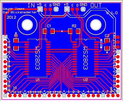
With the large channel count required to handle 1,512 channels. I ended up using WS2803 IC. This IC works out very well since it has 18 outputs. So each candy cane would require one WS2803 chip. To make this IC work, it doesn’t require too many extra components, thus not needing a very large box to house the controller. I’m using the TA-200 enclosures to house the custom made PCB. Each PCB will have two WS2803 chips that will control two candy canes. That enclosure is still big enough to place additional PCB’s. Each enclosure will hold 3 or 4 PCB’s per 8’ section. That will take care of each section by having only two enclosures with a total of six for the entire project. By knowing this and where the placement of the enclosures will be, this allowed me to know the length of the wires I will need on each led string. I will need four separate lengths of led strings to be able to reach the enclosure from the position of the candy cane.
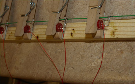
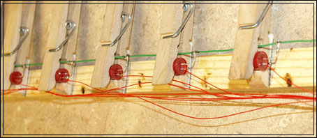
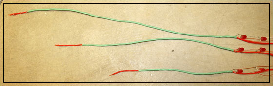
In the past, I have used 30 awg wire wrap for other projects, and with the diameter of the wire and needed 19 wires inside the diameter of the candy cane. It was a good fit. I ended up using eight-teen strands of 30 awg wire to connect the negative side of the LEDS and one length of 22 awg wire to connect the positive side of the LEDS.
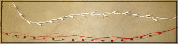
After soldering all those LED strands, I needed to protect the wire pig-tail that was exposed from the end of the candy cane. The diameter of the wire pig-tail was about 3mm. I ordered 5mm green heat shrink in bulk and cut 24 three main lengths and 6 of the other two lengths.
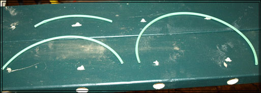
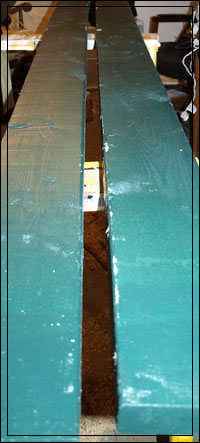
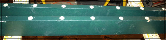
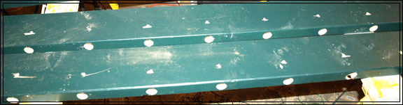
Now on to the wooden bases, there are 3 coats of dark green paint on all 4 sides and the ends of the six 2x6x8’ sections. After they are dry, I measured the centers of the candy canes and equally spaced so that when the two sections are unfolded the end of the candy canes from the first sections match in line of the start of the second sections. The diameter of that hole should be a hair bigger than the diameter of the candy cane. The depth of the hole is 2” deep. I also drilled a ¼” hole from the bottom of the hold on the side to the outside of the 2x6 to allow the wires to go through. After you have that done, I ran a small bead of duck seal around the base of the candy cane to seal it to not allow the water to pass. I chose not to use silicone do to the mess and it would be really hard to take a part if needed to fix a string of LEDS. How you fasten the wire to the 2x6 is up to you. I used the rounded ¼” staples from a staple gun. It’s quick and it doesn’t need to hold them real tight. The TA-200 enclosures are mounted between the 3rd and 4th candy cane and between the 9th and 10th. This will be the same for each section. You will have six candy cane wires going into the first TA-200 enclosure and eight wires for the second TA-200 enclosure.
Once you have your PCB’s ready, you will solder each of the eight-teen 30 awg wires on the outputs of the WS2803. These PCB circuits work off 5 volts. I chose to power two hinged sections with its own 5v 100 watt power supply. The power supply was calculated by the following: Red LEDs are 20ma ea. So 20ma x 18 x 14 x 2 = 10080ma or 10.08A x 5v = 50.4 watts. A rule of thumb is that you should never exceed 80% of the total wattage of the power supply. So a 100 watt power supply you should not exceed 80 watts. I used 12 awg wire to supply the positive and ground from each power supply to each controller. The bigger gauge wire the less voltage loss will happen. The data signal wire daisy chain from controller to controller. Remember each WS2803 IC and PCB has an input and output. You would daisy chain from the output from one WS2803 to the input of the next WS2803, etc. I will use one ECG-P2 from J1sys to supply the data signal to all 1512 channels.
| |
|
|
|